
![]()
![]()
![]()
![]()
![]()
![]()
![]()
Sine Wave Dimming
For a class on lighting technology, Casey wrote a report on exactly how the technology of sine wave dimming works. In the process of writing this report, Casey realized that there was little to no resources that would explain how this technology works in relatively laymen's terms (note: a laymen in this case would be a lighting designer rather then an electrical engineer. There is definitely some knowledge of electricity and theatrical dimming that is taken for granted), so after presenting the report he decided to post this report online... here. So, enjoy. Please remember who wrote it, and cite your sources appropriately.Click Here to View the Accompanying PowerPoint Presentation
(Note: This must be viewed with IE)
Autotransformers used resistive dimming to reduced voltage by lowering
the amplitude of the Alternating Current (AC) sine wave. This however
transferred all of the excess voltage into heat, creating unnecessary
power consumption. Ultimately, it was the inability to control them
remotely that brought about a need for a better alternative, found in
the Thyratron Tube, which was operated via a control signal which was
issued from a control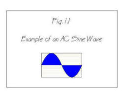 board. This control signal was a simple 10v direct current (DC) signal,
and so long as you could connect the board with the dimmers with two
wires per dimmer the board could be located elsewhere in the theatre.
This change solved the control issue, and happened to be more efficient
as well, but as the industry moved into the age of dimmers that
rectified the sine wave we lost that smooth sine wave that resistive
dimmers output and as the industry later transitioned into solid state
electronic dimmers such as the silicon-controlled rectifiers (SCR) and
later solid-state relays (SSR), we never got back that natural sine wave
output by resistive dimmers.
board. This control signal was a simple 10v direct current (DC) signal,
and so long as you could connect the board with the dimmers with two
wires per dimmer the board could be located elsewhere in the theatre.
This change solved the control issue, and happened to be more efficient
as well, but as the industry moved into the age of dimmers that
rectified the sine wave we lost that smooth sine wave that resistive
dimmers output and as the industry later transitioned into solid state
electronic dimmers such as the silicon-controlled rectifiers (SCR) and
later solid-state relays (SSR), we never got back that natural sine wave
output by resistive dimmers.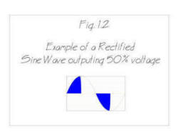
Our rectification solution to the need for dynamically controlling voltages in the entertainment industry has caused some problems over the years.
Sine Wave Dimming is a type of electrical dimming known to the
engineering world as Pulse-Width Modulated (PWM) Dimming. PWM
dimming is a form of AC dimming which allows you to adjust the current
provided to the load downstream of the dimmer just as with the
conventional method of using SSR dimmers, but by using a completely
different output waveform. The waveform created by PWM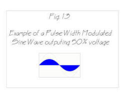 dimming [Fig.. 1.3] mimics that of non-dimmed AC voltage [Fig. 1.1] with
the one exception that the PWM waveform has a lower amplitude, meaning
that the overall voltage is lower. In SSR dimming, the waveform is
chopped [Fig. 1.2] and this creates many problems within the context of
a theatrical lighting package. By modifying the waveform, PWM dimmers
can reduce the audible sound the physical dimmer makes itself, the sound
filaments make inside the lighting instruments lamps, and the
radio-frequency noise created by the chopped sine wave output of
tradition SCR and SSR dimmer types. This creates a quieter atmosphere
in the theatre as well as increases lamp life and decrease strain on the
neutral leg going into the dimmer rack.
dimming [Fig.. 1.3] mimics that of non-dimmed AC voltage [Fig. 1.1] with
the one exception that the PWM waveform has a lower amplitude, meaning
that the overall voltage is lower. In SSR dimming, the waveform is
chopped [Fig. 1.2] and this creates many problems within the context of
a theatrical lighting package. By modifying the waveform, PWM dimmers
can reduce the audible sound the physical dimmer makes itself, the sound
filaments make inside the lighting instruments lamps, and the
radio-frequency noise created by the chopped sine wave output of
tradition SCR and SSR dimmer types. This creates a quieter atmosphere
in the theatre as well as increases lamp life and decrease strain on the
neutral leg going into the dimmer rack.
How does it work?
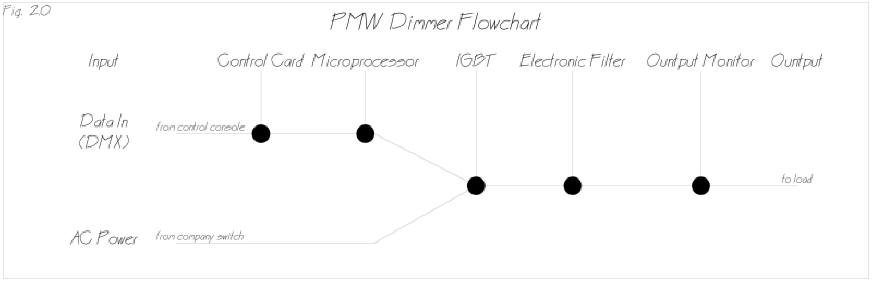
The technology in a sine wave dimmer includes one input for power input into the circuit (120v @ 60Hz in the US) and a control input into the microprocessor (DMX512). The control module takes the control input and translates it into instructions for the microprocessor to translate into a signal that tells the IGBT when and for how long to open the gate. When the gate is open, the AC voltage flows through and into the passive electronic filter that blends the AC voltage into a smooth sine wave of a lower voltage. That lower voltage AC power goes through an output monitor and then out to the load. [Fig. 2.0] The microprocessor takes the control signal and translates it into instructions that adjust the lengths of the ‘on’ and ‘off’ cycles (or duty cycle) in such a way so that the output is a digital control signal that tells the gate how to allow only enough power through the gate to create the desired voltage.
The input of this type of
dimmer is identical to previous generations of dimmers in that is will
read the DMX512 control protocol which is currently industry standard.
This makes them backward compatible, and makes installation into a
current system possible. This input signal goes into a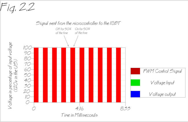 controller, which translates it into a set of instructions determining
the duty cycle (or the ratio of ‘on’ to ‘off’) of the circuit. These
instructions are input into a microprocessor, which takes the
instructions and creates a binary control signal [Fig. 2.2], which is
then sent to the insulated gate bipolar transistor (IGBT).[1]
The microprocessor does this via its internal clock, which is reset at
the end of each duty cycle period. The microprocessor is constantly
checking its clock against the current number given to it by the
controller. If the clock exceeds the number in the instructions, it
sends a control signal telling the IGBT to turn off. At the end of the
duty cycle period, the microprocessors clock is reset and is sends a
control signal telling the IGBT turns on again. After everything is
reset, the process starts over again. This process happens about 50,000
times per second.[2]
controller, which translates it into a set of instructions determining
the duty cycle (or the ratio of ‘on’ to ‘off’) of the circuit. These
instructions are input into a microprocessor, which takes the
instructions and creates a binary control signal [Fig. 2.2], which is
then sent to the insulated gate bipolar transistor (IGBT).[1]
The microprocessor does this via its internal clock, which is reset at
the end of each duty cycle period. The microprocessor is constantly
checking its clock against the current number given to it by the
controller. If the clock exceeds the number in the instructions, it
sends a control signal telling the IGBT to turn off. At the end of the
duty cycle period, the microprocessors clock is reset and is sends a
control signal telling the IGBT turns on again. After everything is
reset, the process starts over again. This process happens about 50,000
times per second.[2]
This is somewhat similar to SSR dimmers, except that SSR dimmers duty cycle period was set to a static time of one half of one period of the AC power period. In the US with 60Hz power, SSR dimmers duty cycle period is 120Hz, since the triac fires once per phase, or 120 times per second. PMW dimmers have a duty cycle period that is thousands of time shorter then that of SSR dimmers, in the 50KHz range.[3] What this means for the voltage output is that the passive filtering now is filtering a waveform that is of a much higher resolution. This allows
the filter to smooth
the output so successfully that, for all intents and purposes, it is
just an AC waveform at a lower amplitude and subsequently lower voltage
AC power. It does this by constantly modifying the duty cycle.
Remembering that voltage is measurement of the average of the space
under the curve, sine wave dimmers are calibrated to output the same
amount under the curve as its analog counterpart of the same voltage.
However, as with all that is digital, the dimmer only works in terms of
no voltage or full voltage. While there are many different types of
PWM, the kind used in dimmers for the entertainment industry are such
that when full voltage is given, it simply opens the gate and allows all
of the voltage input into the system at that moment to pass through.
Mathematically this operates like a multiplier. If the PWM duty cycle
is .5 (or ‘on’ for one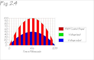 half of the duty cycle period), then you simply have to multiply that by
the input voltage to get the output voltage. So, if the controller’s
instruction is “5” and the counter in the microprocessor counts to “10”
then the duty cycle is “.5”. This means that when the counter reaches
“6” it tells the IGBT’s gate to close. This happens all throughout the
AC sine wave, so when the gate is open it is only outputting that which
is coming into the circuit through the company switch and when it is
closed it is outputting nothing. But since it is on half the time and
off half the time, and this happens thousands of time per AC voltage
period the resolution is such that the output averages out to be 50% of
the input, or the
half of the duty cycle period), then you simply have to multiply that by
the input voltage to get the output voltage. So, if the controller’s
instruction is “5” and the counter in the microprocessor counts to “10”
then the duty cycle is “.5”. This means that when the counter reaches
“6” it tells the IGBT’s gate to close. This happens all throughout the
AC sine wave, so when the gate is open it is only outputting that which
is coming into the circuit through the company switch and when it is
closed it is outputting nothing. But since it is on half the time and
off half the time, and this happens thousands of time per AC voltage
period the resolution is such that the output averages out to be 50% of
the input, or the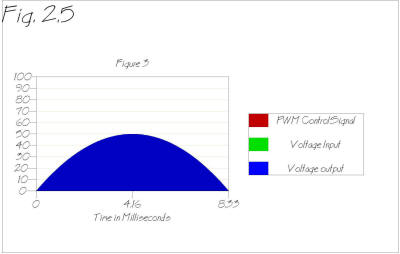 same percentage as the PWM duty cycle. When set to 50% output,
autotransformers output 50% of the input, all of the time. When set to
50% output, PWM dimmers output all of the voltage for 1/50,000 of a
second and then none of the voltage for 1/50,000 of a second [Fig. 2.4]
and then are filtered such that even the miniscule gaps created by this
digitizing are smoothed out [Fig. 2.5]. The final step in the process
is that the dimmers sample the output voltage and sends the information
gathered back to the controller. Some PWM dimmers have the ability to
adjust dynamically the output if it is not correct. Such as if the
dimmer is set to 50%, but it is only outputting 50v the controller can
see this and adjust the control signal so that the dimmer outputs the
proper 60v. This is helpful if the dimmers are in a location where
there is soft power service so a steady 120v is not coming in. Also,
this allows the dimmer to react differently to different loads. Since
voltage output varies under load, this allows the dimmers to output the
appropriate voltage regardless of the load by dynamically adjusting the
voltage as the load changes. If the were to have a 75w 120v birdie
running at 50% on a 2.4k PWM dimmer and you added a 2k fresnel, the
birdies light output would not change at all. This eliminates the
problems overcome by ghost loads years ago. This also is how PWM dimmer
can dim so well in the low ranges, where other dimmers have problems
accurately and consistently outputting the proper power. This
monitoring step also acts as an additional over current protection. If
the dimmer sees that it is somehow outputting more then the current it
is rated for it will shut off, however this is not a replacement of
traditional electromagnetic breakers where the voltage is input into the
dimmer, as this breaker protects not only the load placed on the dimmer,
but also the dimmer and all of its delicate circuitry.
same percentage as the PWM duty cycle. When set to 50% output,
autotransformers output 50% of the input, all of the time. When set to
50% output, PWM dimmers output all of the voltage for 1/50,000 of a
second and then none of the voltage for 1/50,000 of a second [Fig. 2.4]
and then are filtered such that even the miniscule gaps created by this
digitizing are smoothed out [Fig. 2.5]. The final step in the process
is that the dimmers sample the output voltage and sends the information
gathered back to the controller. Some PWM dimmers have the ability to
adjust dynamically the output if it is not correct. Such as if the
dimmer is set to 50%, but it is only outputting 50v the controller can
see this and adjust the control signal so that the dimmer outputs the
proper 60v. This is helpful if the dimmers are in a location where
there is soft power service so a steady 120v is not coming in. Also,
this allows the dimmer to react differently to different loads. Since
voltage output varies under load, this allows the dimmers to output the
appropriate voltage regardless of the load by dynamically adjusting the
voltage as the load changes. If the were to have a 75w 120v birdie
running at 50% on a 2.4k PWM dimmer and you added a 2k fresnel, the
birdies light output would not change at all. This eliminates the
problems overcome by ghost loads years ago. This also is how PWM dimmer
can dim so well in the low ranges, where other dimmers have problems
accurately and consistently outputting the proper power. This
monitoring step also acts as an additional over current protection. If
the dimmer sees that it is somehow outputting more then the current it
is rated for it will shut off, however this is not a replacement of
traditional electromagnetic breakers where the voltage is input into the
dimmer, as this breaker protects not only the load placed on the dimmer,
but also the dimmer and all of its delicate circuitry.
Traditional SCR and SSR dimmers ‘chop’ the AC sine wave in such a way that the output waveform is noticeably deformed. [Fig. 1.2] While this is an acceptable deformation when working with resistive loads such as the tungsten-halogen lamps used in most theatrical lighting instruments because they simply need power to give resistance to so that they will heat up to the point of incandescence, this does create a byproduct: harmonics. Traditional AC dimmers that chop the sine wave create filament noise. This is created by the chopped sine wave. The speed at which the sine wave is chopped in SSR dimmers is fast enough to not be noticeable because the filament cannot cool down quickly enough to visibly flicker. It is however at a speed that causes the filaments themselves inside the lights to vibrate and this vibration is loud enough to be heard by the audience. This audible vibration can also be heard from the dimmer itself as the abrupt fluctuations of current can cause the choke and other electrical components to vibrate inside the dimmer itself. Since PWM dimmers do not chop the sine wave, the filaments do not vibrate at all. Because of this, there is virtually no noise created by lights dimmed by PWM dimmers or from the dimmers themselves, even in the 50% range.[4]
The deformed waveform of SSR dimmers has a more violent effect on the rest of the lighting package. [Fig 4] If all three of the phases are simultaneously faded up, you will get what is known as triplin harmonics. Three-phase power is designed so that the three phases cancel each other out and in an ideal situation there is no load on the neutral at all. [Fig. 4.1] Assuming you have an unencumbered company switch to your dimmers,
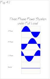
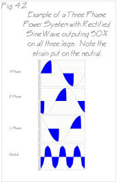
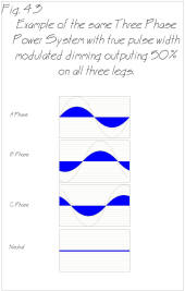
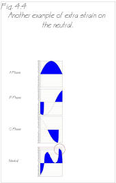
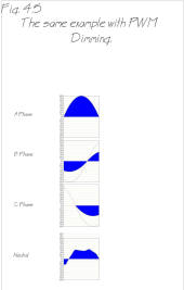
and your dimmers are at full and at maximum capacity; if you dim everything down to 50% you will be putting substantial strain on the neutral. [Fig. 4.2 & 4.3] This strain is not only present in your system, but also in the neutral run back into the grid putting strain on the entire grid. In the same scenario, if you were to fade up all the lights on the A phase to full but leave all the lights on the B and C phases at 50% you would find an even larger problem. [Fig 4.4 & 4.5] You are now putting as much as 115% of its rated current on the neutral. If in the same scenario you had two phases at full capacity and one at zero capacity you could get up to 140% the rated current. Contemporary lighting packages are designed to consider this and are installed with larger neutral legs then hot legs. In these same scenarios the PMW dimmer puts much less strain on the neutral because of its smooth waveform and creates a negligible amount of triplin harmonics[5]. [Fig. 4.3 & 4.5] This lack of triplin harmonics allows PWM dimmers to be installed with neutrals that are much smaller then those in a system that might encounter the extra neutral load of wave chopping dimming.[6]
When using the same power system as the sound system, you will probably run into problems with a ‘60 cycle hum’ in the sound system. This is because of the same triplin harmonics explained above, except that this specific problem is due to the harmonics effect on the ground in the buildings power system. This extreme load on the neutral causes some of the excess current to go through the ground and if the lighting systems ground is shared with the sound system[7] ground this interference can travel from to the chassis ground on the sound components and from there get into the signal ground and interfere with the sound signals creating that 60 cycle hum.
It is also possible for these triplin harmonics to travel directly to the signal ground located in sound cables if they are run parallel and in close proximity to the lighting cables. When the load attached to the lighting cables is dimmed, this electrical noise in the lighting cables can induce a current in the signal ground of the sound cables and this will also cause 60 cycle hum in the sound system. [8]
SSR dimmers are unable to dim certain types of loads such as inductive loads. Their unnatural waveform is unable to sustain the inrush required to cause some ballasts to fire on fluorescent lights and this waveform can damage the sensitive electrical components in electrical motors. But since PWM dimmers exactly replicate the waveform of a lower voltage, almost all inductive loads can be dimmed by a PWM dimmer. This is an advantage that creates is the ability to use your theatrical dimmers for more then just lighting, for instance a PWM dimmer could be used to variable control a motor in a set piece.
PWM dimmers are key in the in the development of LED (light emitting diode) lighting for the theatre. LEDs do not respond well to less voltage then they are rated for, so to dim them you are required to always give them full voltage and just vary the duty cycle to dim the LED. However, to dim LEDs you must use dimmers that are not filtered so that the actual voltage sent to the LEDs is still chopped. This still causes the noise problems associated with chopping the sine wave, but since LEDs are currently available in the 2w to 5w range, this noise is still well below acceptable levels. This means that you need to use special PWM dimmer with LEDs so that they are designed to send this chopped signal directly to the lamp. Many of the currently available LED theatrical fixtures, such as those from Color Kinetics, utilize PWM dimming to vary the output of the LEDs in their fixtures.[9]
Another main advantage of PWM dimming is that they are vastly more efficient then most other forms of dimming. Autotransformers varied voltage through the use of resistance, but this meant that regardless of the load downstream of the dimmer, all of the power would be used if the dimmer was set anywhere between 1% and 100%. CD80 dimmers[10] tout a 97% efficiency[11], but this efficiency is only available by utilizing the with low rise time version of the dimmer, which operate louder then the higher rise time versions. Sine wave dimmers are more efficient then comparable SSR and SCR dimmers, they are able to operate much faster, be much quieter, and still achieve the same efficiency.
The benefits of the technology speak for themselves, but the bottom line is always price, and that is where the downfall of the sine wave dimmer lays. Sine wave dimmers cost several times that of an SCR or SSR dimmer, and the benefits are not tangible enough justify the upgrade for many potential buyers. This price is due to the fact that many of the parts required to make a sine wave dimmer must be custom built. This is in an industry, which must constantly make creative use of parts from other industries simply to get around the limitations in place due to the relatively small demand of out industry compared to the computer industry. This means that unless they are going to sell in quantities well above where they are, the price will continue to be substantially higher then the alternatives.
It is difficult to see the future of the sine wave dimmer. The price is a huge sticking point for most, but technology often goes down in price quickly. Dimmers are needed in new performance spaces, but when ACN is released in the near future it may entice many upgrades and that may provide sine wave dimmers with the medium for widely showing the industry the benefits of the technology, which could lead to them becoming mainstream much more quickly then most technological advances in the lighting technology field. But regardless of the time frame, it is safe to say that any technology that offers the benefits of the sine wave dimmer is not going to go away.
[1] SST Sine Wave Dimmers. n.d. Strand Lighting. 12 May 2007 <www.parlights.com/parlights/Downloads_files/strand/Dimming/Sinewave%20Dimmer%20Technology.pdf>.
[2] U.S. Patent Office. US 7,019,469 B1. Filed Oct 21, 2004, Issued Mar 28, 2006.
[3] U.S. Patent Office. US 7,019,469 B1. Filed Oct 21, 2004, Issued Mar 28, 2006.
[4] In dimmers that chop the sine wave such as SCR or SSR dimmer, the lights would hum the loudest when dimmed to 50% because sine waves peak half way through their cycle as the reach their crest and begin returning to 0v. This peak half way through the wave forms means that the amplitude difference between on and off is greatest when the dimmer is set to 50% and therefore the harmonics, for the most part, are the worst when the dimmer is set to 50%.
[5] SST Sine Wave Dimmers. n.d. Strand Lighting. 12 May 2007 <http://www.parlights.com/parlights/Downloads_files/str...>.
[6] Engdahl, Tomi. “Light Dimmer Circuits.” 12 October 2006. <http://www.epanorama.net/documents/lights/lightdimmer.html>
[7] The sound and lighting systems should not share a ground, but things happen that should not and this is often a problem, especially in temporary setups such as football stadiums, where not as much forethought has gone into how to power all the different systems involved in the production.
[8] Sound System Interconnection. Apr. 2007. Rane Corporation. 15 May 2007 <http://www.rane.com/note110.html>.
[9] n.d. Color Kinetics. 3 Feb. 2007 <http://www.colorkinetics.com/corp/whyck/>.
[10] CD80 dimmers are an SSR dimmer made by Strand Lighting.
[11] Strand Lighitng. n.d. Texas Scenic Company, Inc.. 15 May 2007 <http://www.texasscenic.com/strand_lighting.html>.
Click Here to View the Accompanying PowerPoint Presentation
(Note: This must be viewed with IE)